5.1.2 METHODS
5.1.2.4 MODEL METHODS
The Model selection on the top menu deals with specific methods involving the present state of the design. View part and view features use the MSee server and are described in the next section.
View mold dimension and view machine selection result in the displays of Figure 45 and Figure 46. In this example, the mold evaluation method has been invoked. The results are displayed in Figure 44 (a) for 4 cavities per mold. The mold width is calculated to be 28.07 inches while the mold height is 37.05 inches. Note that the mold machine tonnage specification, which is dependent on the material type, and the machine clamping tonnage requirements have been determined as well.
The mold machine layout reveals with an exclamation mark (!) on a raised tile the six machines on the plant floor can handle this particular mold. The selected machines are listed and machine parameters for each particular machine can be obtained either by clicking on the machine box icon or on the text selection.
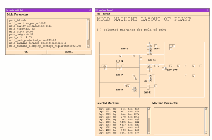
Figure 46 shows the mold dimension and machines available for 2 cavities per mold. Note that the number of available machines is increased. Various "what-if" scenarios can be created by changing the number of parts in a mold or the part orientation. These can be done in a matter of seconds.
Figure 45 Mold Parameter and Machine Selection Layout Windows
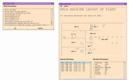
Figure 46 Reiteration of Mold Parameter and Machine Selection Layout
The delete Noodles model selection is present because, once feature extraction and PIMES evaluations had occurred, there might not be a necessity to hold on to the Noodles model, especially considering that an industry model takes up an average of 10 megabytes.
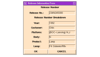
The part parameters, release parameters, and optic parameters are forms for obtaining information specific to the design, with examples in Figure 47, Figure 48, and Figure 49 respectively. A model is not just the CAD model but also must include ancillary information about the design.
The Part Information Form of Figure 47 provides access to the material and geometric properties of a part. The Release Information Form takes the release number of a design, whether included with part information or provided directly to the form, and looks up the various codes from a database. The breakdown is presented to the user in an understandable form.
Figure 47 Part Information Form
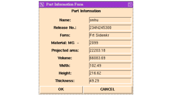
Figure 48 Release Information Form
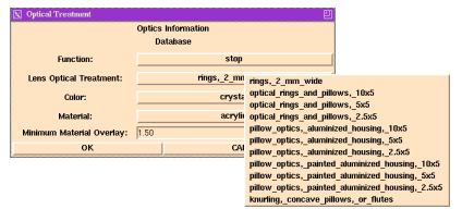
The Optics Information Database Form allows the user to indicate function, lens optical treatment, color, material, and then suggests a minimum material overlay. Menu selections are constrained by previous information. As illustrated in Figure 49, given a sidemarker function, there are only three optical treatment options available. In Figure 50, the signal tail function allows many optical treatment options. These menu options of course are constructed on the fly. The user is never allowed to set up an invalid combination of function, lens treatment, color, and material.
Figure 49 Optical Information with Minimum Material Overlay Determination
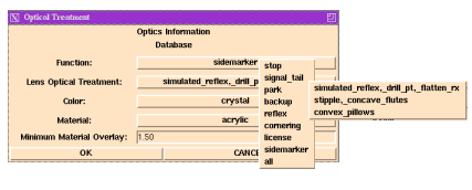
Figure 50 Constraint-Enforced Optical Treatment Selection
