5.1 THE DESIGN PROCESSOR
5.1.1 OBJECTS
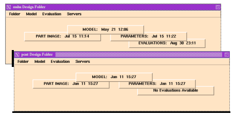
Figure 39 illustrates a "Design Folder" with its menu and its status blocks. Each engineering design is represented by a design folder. A new design folder must be for each new design. The design folder acts as repository for all representations concerning the design. When a design folder is opened, there are two sections evident. The largest section consists of tiles representing the representations involved in the design, including the Noodles CAD model. The top line of the folder indicates applications and methods that can be invoked upon these representations.
Figure 39 Design Processor Folders

There are four tiles representing four classes of representation of the design: the Noodles Model, Part Image, Parameters from feature extraction, and expert system Evaluations. The tiles are visually stacked to indicate which representations must be available before others can be produced. For example, the Noodles model, as represented by the top-most tile, must be present before a part image or feature parameters can be produced. Addition of a representation is as simple as adding and positioning a block. Theoretically, no evaluations can be made available unless the parameter data as represented by the Parameters tile is present, although that is built into the evaluation program and not the representation.