3.2 THE DESIGN FOR MOLDING SYSTEM
3.2.1 DFM INFORMATION FLOW
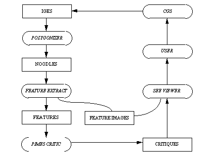
A geometric CAD model provides the starting representation with which DFM may initiate evaluation and the viewing of a part to be manufactured. Figure 13 traces DFM's information flow from the designer's representation, to the final critique of the design, back to the user. Initially, a design is created within a particular vendor's graphic system. In the General Motors Project for which DFM was created, a boundary modeling system known as the Corporate Graphics System (CGS) is used.
The DFM environment requires that the CAD designs at least be in the form of the Initial Graphics Exchange System (IGES). The IGES standard was developed by [SAE 88] as a medium to exchange graphics between proprietary systems. Most CAD systems, including CGS, already provide facilities to translate their representations to and from the IGES standard.
Figure 13 Design for Molding Information Flow

Surface-based CAD models, which use lines, points, and surfaces to define an object do not contain the topological elements required for feature recognition. As seen in Figure 13, the surface-based IGES model is converted to a Noodles model by the Polygonizer application. The Polygonizer application generates a Noodles model as a linear-consistent geometric model based on a boundary representation scheme. The non-manifold surface representation known as Noodles essentially represents a solid model [Choi 89][Gursoz et al 88].
Geometric features are then recognized and extracted from this Noodles representation, with the feature extraction application. Parameters such as draft angle, thickness, and length, are then determined for these features. Feature images are also generated as text files containing data readily interpreted by the "See" viewing application.
Acting upon the feature data, the Plastic Injection Molding Expert System (PIMES) generates evaluations. Violation of a rule results in the formation of a message for the particular violation. This message indicates the cause for criticism and is customized with the appropriate parameters of the offending feature.
Feature images and critiques are used within an interactive viewing application. This application displays the entire model and at the discretion of the user highlights problem features.